
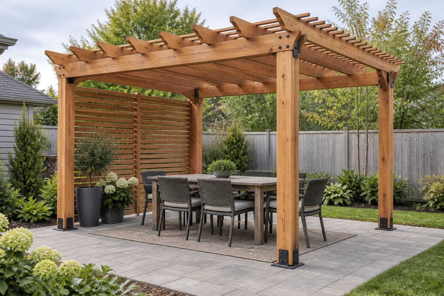
The extra two feet in a 10×12 pergola make a real difference around a six-person table: chairs can move at the ends without landing beneath a beam. The rectangle also creates a natural long axis for a path, view, or run of outdoor furniture.
This version remains completely freestanding. Four independent footings carry the frame, so no ledger penetrates the house. The details below are a construction reference; local frost, soil, wind, spans, lumber grades, and approvals still govern.
Locate utilities and confirm setbacks, easements, height, permit thresholds, and fence or screening rules. The privacy slats add wind area even though they carry no roof load.
Use the long direction for beams and circulation
The roof finishes at 10×12 feet and the post centres form a 9×11-foot rectangle. Paired beams run along the 12-foot sides, keeping the rafter span to the shorter 10-foot direction. The screen fits at one short end where it can hide a neighbour or low sun without closing the principal approach.
Materials and tools
This takeoff suits the shown four-post concept and includes a modest allowance for the screen. Confirm actual spans, treatment compatibility, footing sizes, and connector schedules before placing the order.
| Assembly | Main material | Planning quantity |
|---|---|---|
| Footings | Concrete piers and compacted stone bases | 4, sized locally |
| Posts | 6×6 ground-contact-rated posts | 4 at 10′ |
| Beams | 2×10 exterior-rated beam members | 4 at 12′ |
| Rafters | 2×8 exterior-rated rafters | 8 at 10′ |
| Shade | 2×2 purlins | 13 at 12′ |
| Privacy screen | 2×4 rails and vertical 1×4 slats | 3 rails + about 16 slats |
| Hardware | Standoff bases, through-bolts, rafter ties, structural screws | One complete rated set |
Build from fixed control lines
- Post-hole digger or power auger
- Circular or miter saw
- Drill and impact driver
- Long level or laser level
- Tape, framing square, and string
- Clamps and temporary braces
- Socket set and torque wrench
- Ladders and fall protection
Orientation + layout
Aim the 12-foot axis before you dig
Decide whether the long axis should follow the house, frame a view, or align with a dining table. Also watch the site across a sunny day: because the top purlins run in the 12-foot direction, their shadows move across the short dimension. Once the orientation is settled, string a 9×11-foot post-centre rectangle.
- Place the screened end where it blocks the least winter light.
- Keep the full 10×12-foot overhead envelope inside required setbacks.
- Match the two post-grid diagonals before marking pier centres.
Foundation
Carry each post to a frost-safe pier
Excavate each footing to locally required bearing soil and frost depth. Diameter, reinforcing, and pier weight depend on the soil and wind exposure, so a generic hole size is not reliable. Keep the finished concrete above grade and slope the adjacent patio or soil away.
Align four galvanized standoff post bases precisely to the 9×11-foot grid. Their slots or plates must follow the direction assumed by the approved connection. Do not bury cedar or pressure-treated posts directly in concrete for this detail.
Posts + beams
Build two straight 12-foot beam lines
Brace the four 6×6 posts plumb in both directions, then mark one common beam elevation with a laser or water level. Clamp a 2×10 to each face of both long post rows, creating two paired beams. Equal half-foot end overhangs produce the 12-foot beam envelope from the 11-foot post spacing.
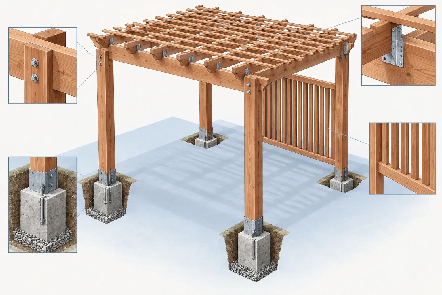
Through-bolt the assemblies using the approved diameter, washers, edge distances, and spacing. Add structural knee braces without cutting deeply into the posts. Leave temporary ground braces until the rafters and permanent lateral system are complete.
Rafters
Cross the short span with eight rafters
Use one straight 10-foot 2×8 as the rafter pattern, including any shallow end cut. Lay out eight rafters evenly over the 12-foot beam length. Equal end margins and a consistent layout from the same beam end are more important than forcing an exact nominal spacing.
- Check the paired beams remain parallel.
- Seat every rafter fully on both beam lines.
- Install a rated uplift tie at every crossing.
The shown 2×8 rafters and 2×10 paired beams are a reference concept. Verify their grade, species, span, wind, snow, and any future canopy load locally.
Shade
Run purlins along the long axis
Set thirteen 2×2 purlins across the rafters, running the full 12-foot length. The shown spacing makes a consistent open lattice, not a weatherproof roof. Test a short loose section at midday before fixing the whole set; small spacing changes noticeably alter the shadow below.
If adjustable shade is the priority, use a purpose-made exterior canopy system with published attachment and wind limits. Do not staple fabric to the frame or leave a sail-like cover deployed in severe weather.
Privacy screen
Keep the end screen ventilated and independent
Fit three horizontal 2×4 rails between the posts at one short end, keeping the lowest rail above splashback and clear of post-base hardware. Space roughly sixteen vertical 1×4 slats consistently, with enough opening to relieve wind and allow the wood to dry. Seal every cut before installation.
Stop the screen below the beam connections and do not fasten through critical bolts or connector plates. The slats are replaceable privacy infill; the primary frame still relies on its approved bracing or moment connections.
Finish
Let the wood dry and keep water moving
Ease edges and apply an exterior finish only when the wood is within the coating manufacturer’s moisture range. Keep post bottoms ventilated, clean sawdust from connector pockets, and avoid trim that traps water. Recheck bolts and screen fasteners after the first wet-and-dry season, then inspect them each spring.
Make it site-specific
Fit the long axis and screen to your yard
Adjust the post positions, foundation, shade direction, and screened side around your real property, then coordinate the result with boundaries and permit rules. HomeCat keeps the outdoor structure and site plan in one project.
Customize these pergola plansCommon questions
Before you start
Does a 10×12 pergola need a permit?
It may. Rules vary with area, height, setbacks, attachment, screening, and roof coverage. Ask the local authority before excavation.
Which way should the rafters run?
In this layout the paired beams run along the 12-foot sides and the eight rafters cross the shorter 10-foot span. Top purlins then run parallel to the beams.
Does the screen replace knee braces?
No. Treat it as non-structural infill unless an engineer designs it otherwise. The primary frame still needs approved lateral resistance.
Can I add a solid or retractable roof?
Only after redesign. A cover changes snow, rain, gravity, and wind loads and may reclassify the project as a patio cover under local rules.